External User Interface
The Bottom Side of EVB and It’s external Interfaces are as follow.
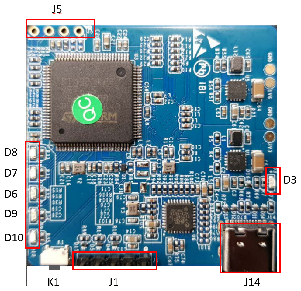
1. Power Supply
| Power | Description | |
| Power Input Voltage | 3.3V ~ 5.5V. | |
| Default Power Input Method | J14 USB Type-C interface. | |
| Secondary Power Input Method | Pin 1 and Pin 2 of J1 interface. | |
| Operation Indicator |
After normal power up, D3 (power indicator LED) shows green and keeps on, D8 (normal operating indicator LED) shows green and blinks. |
|
2. USB Type-C
| PIN | Name | PIN | Name | |
| A1 | GND | B12 | GND | |
| A4 | VBUS | B9 | VBUS | |
| A5 | CC1 | B8 | SBU2 | |
| A6 | DP1 | B7 | DN2 | |
| A7 | DN1 | B6 | DP2 | |
| A8 | SBU1 | B5 | CC2 | |
| A9 | VBUS | B4 | VBUS | |
| A12 | GND | B1 | GND |
3. LED and Switch
| Reference No | Name | Description | |
| K1 | Switch | Reset switch | |
| D3 | Green indicator LED | 3.3V power supply indicator | |
| D6 | Green indicator LED | Radar data reception overflow indicator | |
| D7 | Green indicator LED | Radar data index error indicator | |
| D8 | Green indicator LED | Normal operating indicator | |
| D9 | Green indicator LED | Radar data transmission overflow indicator | |
| D10 | Green indicator LED | MCU indicator which i |
4. J1 → UART and I/O Interface
| PIN | Name | Function | Description | |
| 1 | 5V | Power supply input | Vcc: 3.3V~5.5V, Typ.:5V | |
| 2 | GND | Connect to ground | IO voltage: 0~3.3V | |
| 3 | O_T1 | Can be configured as UART_TX or IO, cannot be configured as UART_TX at the same time with Pin O_T2. Default set as UART_TX |
IO voltage: 0~3.3Vn | |
| 4 | RX | UART_TX | IO voltage: 0~3.3V | |
| 5 | O_T2 | Can be configured as UART_TX or IO, cannot be configured as UART_TX at the same time with O_T1. Default set as IO |
IO voltage: 0~3.3V |
5. J5 → SWD Interface
| PIN | Name | Function | Description | |
| 1 | GND | Connect to ground | ||
| 2 | DIO | Data input/output | IO voltage: 0~3.3Vn | |
| 3 | CLK | Reference clock signal | IO voltage: 0~3.3V | |
| 4 | 3V3 | Reference power supply output | Ref. voltage: 1.8~3.6V, Typ.: 3.3V |
![]()
Radar Sensor SoC & Module
![]()
WiFi IoT Module
![]()
5G/LTE/CAT-M1/NB-IoT
![]()
WiSUN/HaLow/Thread Module
![]()