
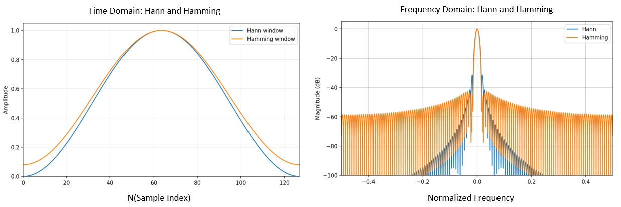
| Window | Window Function(HANN, Hamming) | |
 |
 |
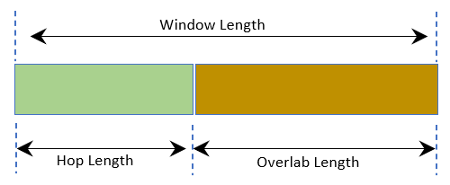
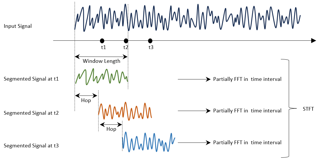
| Sliding window by hop length and Segmenting Signal | ||
 |
2. Principle
STFT operates by applying a window function to the signal and computing the Fourier Transform within each windowed segment.
The window typically overlaps as it slides over time, allowing continuous tracking of frequency changes and improving temporal continuity.
|
FFT for each time segment -> Spectrum |
||
|
|
||
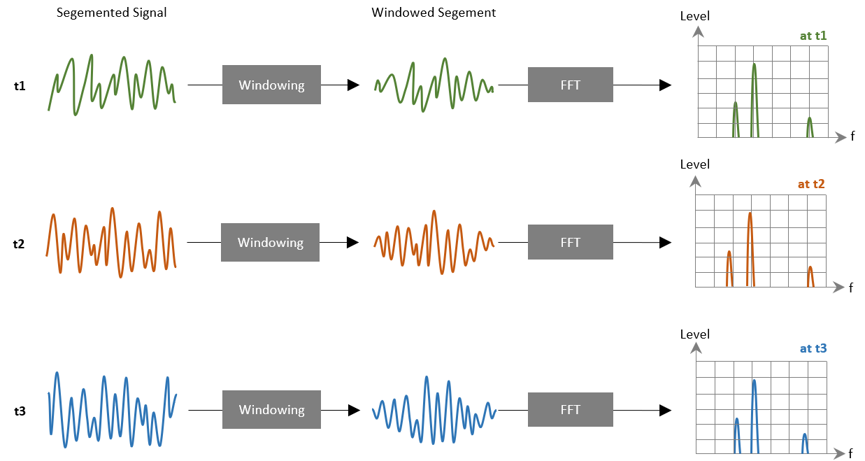
3. Representation
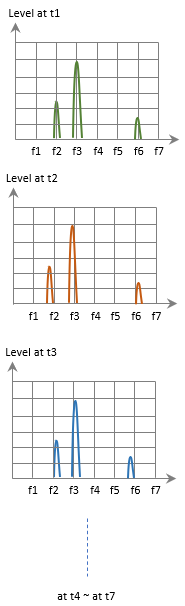
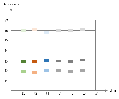
The result of STFT is represented as a spectrogram, which shows how the magnitude of frequency components varies over time.
The color intensity represents the energy level at each time and frequency.
| Spectrum at each time | Spectrogram | ||
 |
 |
The intensity is the energy level at each time and frequency. |
4. Interpretation
In the spectrogram, high-intensity regions represent dominant frequency components at specific times.
The repeating patterns over time indicate periodic behavior,
while vertical spreading patterns reflect transient events and short-duration changes in motion.

5. Radar Application
FFT shows only the overall frequency content of a signal,
since it analyzes the entire signal as a whole, resulting in the loss of time information and making it impossible to determine when those frequencies occur.
In contrast, STFT is more effective at detecting micro-Doppler effects and transient events by capturing how frequency components change over time.
This includes detailed motion patterns such as human walking (e.g., arm and leg movements),
rotating objects like propellers or fans, and short-duration target behaviors that appear as time-varying frequency signatures.


Radar Sensor SoC & Module

WiFi IoT Module

5G/LTE/CAT-M1/NB-IoT

WiSUN/HaLow/Thread Module
