
Angle In FMCW Radar
| 1 | When two or more receiving antennas are spatially arranged, they occupy different physical positions. | |
| 2 | As a consequence, the propagation path length of the electromagnetic wave differs for each antenna | |
| 3 | As a result, the signals received at different antenna positions exhibit phase differences at the same observation time. |

The phase difference information between two receiving channels exists in all output of mixer, Range FFT, and Doppler FFT.
However, the reliability of phase difference detection is increased as the stage is proceeded.
Therefore, The phase difference estimation is most accurate and stable when performed using the RD map after the Doppler FFT.
| Seen at the mixer output | Seen at the Range FFT output | Seen at the Doppler FFT output |

| Hard to isolate target | Range-based target isolation | Range–Doppler target isolation | |
| s2 and v3 unseen by range isolation | v1 and s1 unseen by velocity isolation |
| Phase estimation at | Description | |
| Mixer Output |
Most difficult to detect, because noise and signal components from all ranges and velocities are mixed together (i.e., targets with unspecified distances and velocities are superimposed). |
|
| Range FFT Output |
Still difficult to isolate reliably for a specific target, since stationary objects, moving objects, and multipath components coexist within the same range bin. |
|
| Doppler FFT Output |
Most reliable, because a target with the same range and Doppler(i.e., the same distance and velocity) is selected, and the phase components of other targets are effectively separated. |
1. Signal Flow and Processing
The signals received at different antenna elements exhibit spatial phase differences at the same observation time.
Since the Doppler FFT is a linear operation performed independently on each antenna channel,
the resulting Range–Doppler bins preserve the inter-antenna phase differences, which can be exploited for angle estimation.


2. Angle Formula
The phase difference can be calculated from the RD maps generated by the two receive channels (Rx1 and Rx2)
for the same range–Doppler cell.

| Angle |  |
Δϕ Measured value with range-doppler map. λ Wave Length d Antenna to Antenna distance (Defined by Design) |
|
| Resolution | 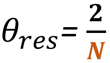 |
Number of Antennas limit the resolution between 2 objects
N Number of Antennas (Defined by Design) |
|
| Max Limit | 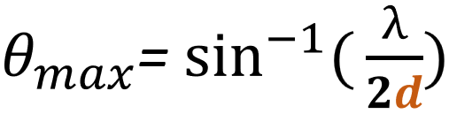 |
Antenna-to-Antenna distance limit the measurable max FOV
λ Wave Length (Defined by Design) d Antenna to Antenna distance (Defined by Design) |

Radar Sensor SoC & Module

WiFi IoT Module

5G/LTE/CAT-M1/NB-IoT

WiSUN/HaLow/Thread Module
