Radar Report Data
Host MCU can receive one of three kinds of report data types through the serial port from XenD101MM.
Users can repeatedly receive different types of data depending on the working mode.
1. Report Data in Normal Working Mode
In the normal working mode, XenD101MM outputs the detection results via the serial port.
The output data are ON/OFF strings as well as the range gate of the detected target.
Setting Working Mode
| Command | Description | |
| FD FC FB FA 04 00 FF 00 01 00 04 03 02 01 | Enter to Config Mode | |
| FD FC FB FA 08 00 12 00 00 00 64 00 00 00 04 03 02 01 | Normal working mode = 0x0064 | |
| FD FC FB FA 02 00 FE 00 04 03 02 01 | Leave Config Mode |
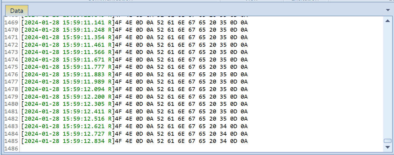
Report Format
| Header | Data | Tailer | |
| 4F 4E 0D 0A | String Message of ” ON/OFF, Range N”, N is range gate number | 0D 0A |
RX Data via Serial Port
Display in Hex
Display in UTF-8 string
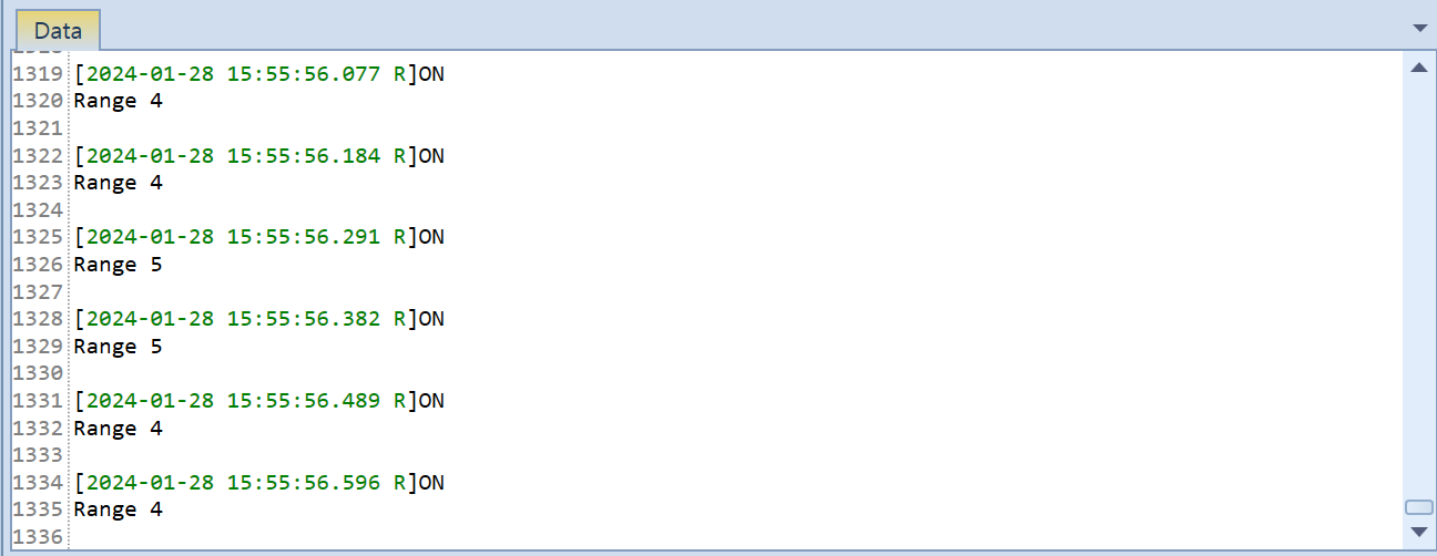
[2025-01-18 17:35:19.065 R]ON
Range 131 :
(QNA) 위와 같이 Range Gate가 아니고 거리로 나오는 경우가 있음?
2. Report Data in Debugging Mode
The RDMAP data of all the range gates of a certain chirp are sent out each time,
i.e., the data of all the 16 range gates of the first chirp will be sent out first, then goes the second chirp, and so on.
Setting Working Mode
| Command | Description | |
| FD FC FB FA 04 00 FF 00 01 00 04 03 02 01 | Enter to Config Mode | |
| FD FC FB FA 08 00 12 00 00 00 00 00 00 00 04 03 02 01 | Report in debugging mode(0x0000) | |
| FD FC FB FA 02 00 FE 00 04 03 02 01 | Leave Config Mode |
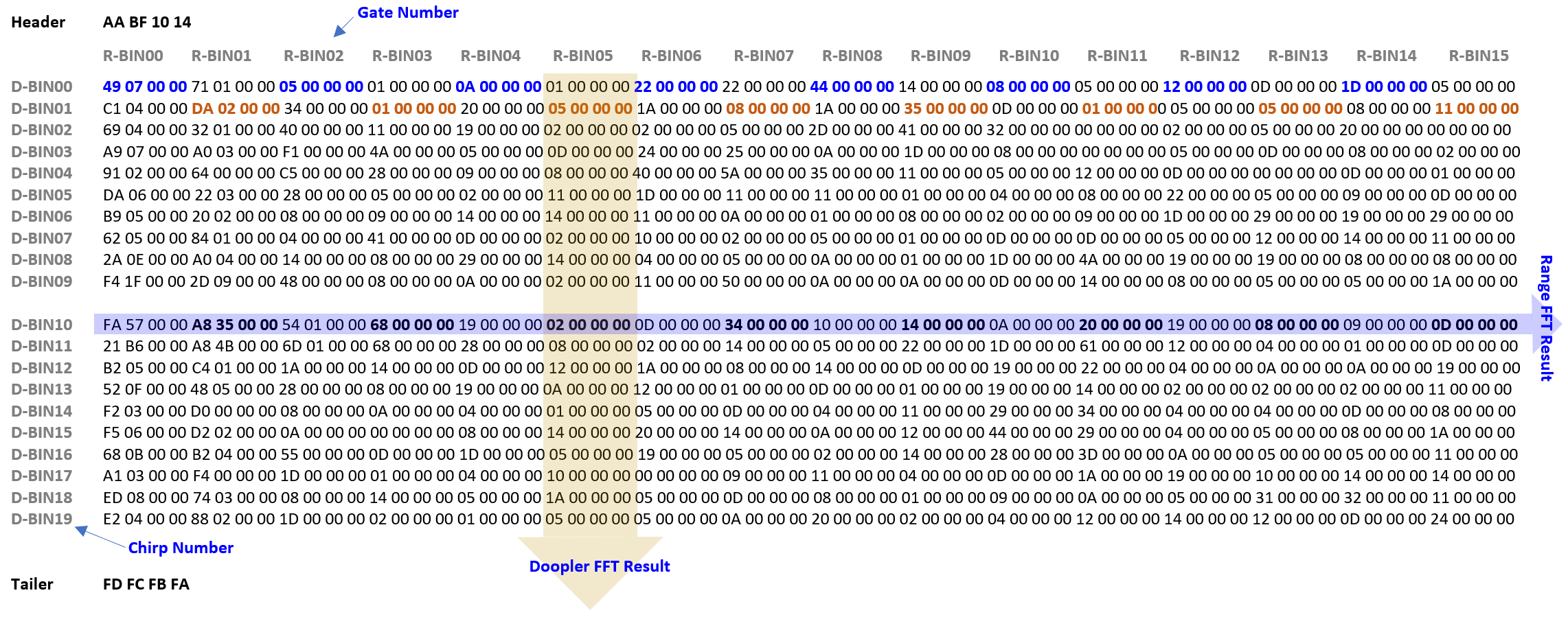
Report Format
| Header | Data | Tailer | |
| AA BF 10 14 | RDMAP: 20(Doppler) * 16 (number of range gate) * 4(square of the amplitude) | FD FC FB FA |
RX Data via Serial Port(Data is re-arranged after RX)
3. Report Data in Reporting Mode
Setting Working Mode
| Command | Description | |
| FD FC FB FA 04 00 FF 00 01 00 04 03 02 01 | Enter to Config Mode | |
| FD FC FB FA 08 00 12 00 00 00 04 00 00 00 04 03 02 01 | Report in reporting mode(0x0004) | |
| FD FC FB FA 02 00 FE 00 04 03 02 01 | Leave Config Mode |
Report Format
| Header | Data Length | Data | Tailer | |||
| Detection Result | Target Distance | Range Gate Energy | ||||
|
F4 F3 F2 F1
|
2 bytes
|
1 Byte ♦ 0x00(no target) ♦ 0x01(target exist) |
2 Bytes
|
32 Bytes (16 * 2 bytes)
|
F8 F7 F6 F5
|
|
RX Data via Serial Port (Data is re-arranged after RX)
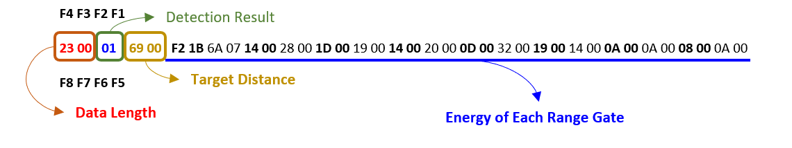
The first range gate is biggest energy(0x1BF2), So made a decision that object is there.
| Length of the data |
The sum of data length of Detection Result, Target Distance, and Energy of Each Range Gate. ex) 00 23 → 35 Byte(Detection Result + Target Distance + Energy of Each Range Gate) |
|
| Detection result |
Whether a target is detected ex) 01 → a human target is detected in current scenario |
|
| Target distance |
The radial distance between the detected target and the radar. ex) 0069 → The radial distance between the detected target and the radar = 105 cm |
|
| Energy of range gate |
The energy value of each range gate (0~15) ex) Range gate 0 = 1BF2, Range gate 1= 076A, Range gate 2 = 0014, Range gate 3 = 0028, etc….., |
![]()
Radar Sensor SoC & Module
![]()
WiFi IoT Module
![]()
5G/LTE/CAT-M1/NB-IoT
![]()
WiSUN/HaLow/Thread Module
![]()