Chirp Modulator
The chirp signal generator consists of a pattern generator and a PLL.
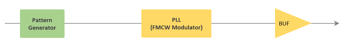
1. Pattern Generator
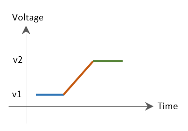
The pattern generator creates a ramp signal that controls frequency variations.
This signal serves as the base waveform to be fed into the chirp modulator.
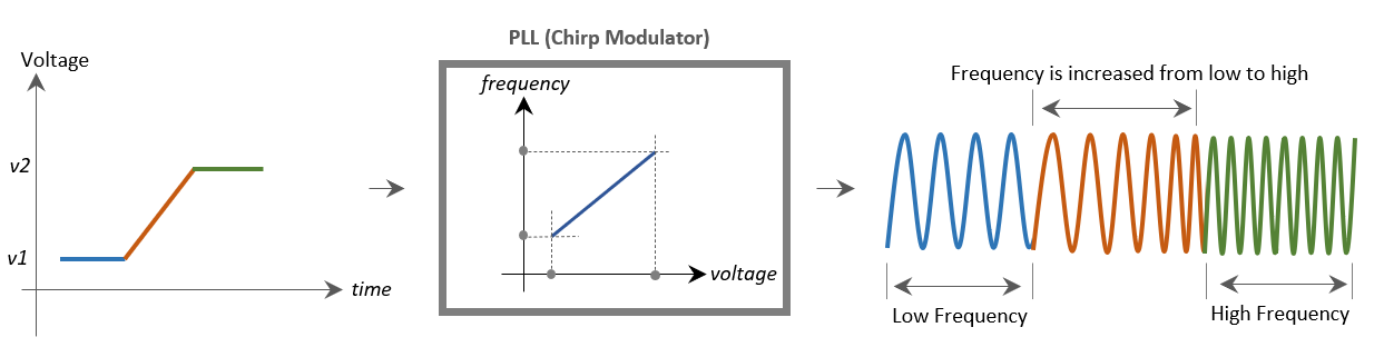
2. PLL
It produces a continuous sinusoidal signal with a frequency proportional to the input voltage.
Specifically, it outputs a signal whose frequency tracks the real-time voltage levels provided by the pattern generator.
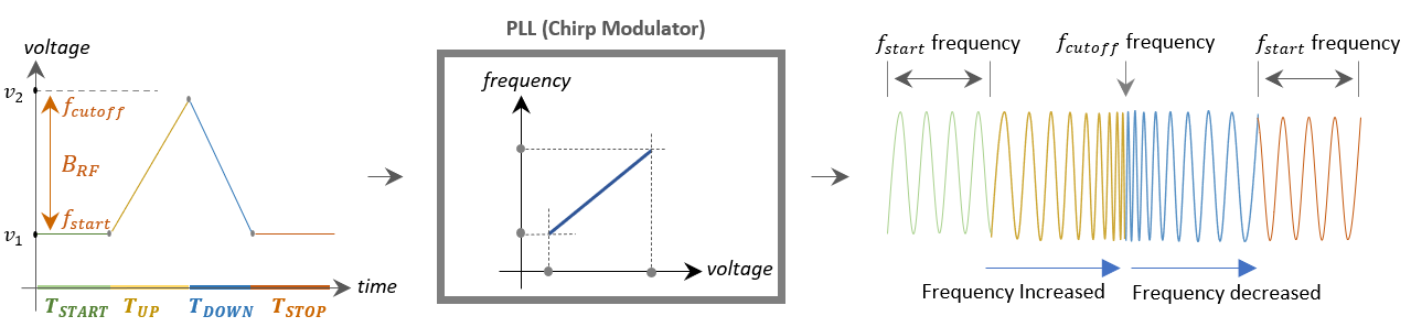
3. Parameters
In the PLL, voltage v1 is converted into the start frequency f_start, while v2 is mapped to the cutoff frequency f_cutoff.
The frequency increases linearly during the positive slope between v1 and v2, and decreases linearly during the negative slope.
![]()
Radar Sensor SoC & Module
![]()
WiFi IoT Module
![]()
5G/LTE/CAT-M1/NB-IoT
![]()
WiSUN/HaLow/Thread Module
![]()