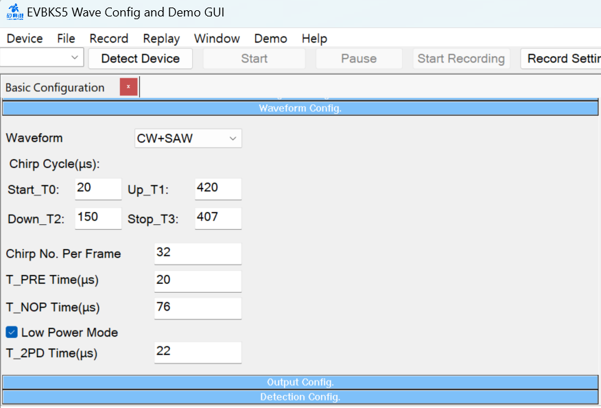
Waveform Configuration
 .
.
1. Waveform
| Parameter | Default | Range | Description | |
|
Output Waveform
|
CW + SAW
|
CW | Continuous Sinusoidal Wave, doppler sensor usage or just for test | |
| CW + SAW |
Up-chirp of pattern SAW for FMCW radar application Mainly used for near-distance object detection(Home IoT) |
|||
| CW +TRI |
Up&Down-chirp of pattern triangle or FMCW radar application Mainly used for distant object detection(Vehicle/Car) |

2. Chirp Cycle
Note. A chirp is the basic cycle that can measure range/distance.
| Parameter | Default [us] | Range [us] | Description |
| Start_T0 | 20 | 20~1,000,000 | Value of “Start” in us |
| UP_T1 | 420 | 128~1,000,000 | Up-chirp duration |
| DOWN_T2 | 150 | 60~1,000,000 | Down-chirp duration, must be no less than T1 x 1/4. |
| STOP_T3 | 407 | 100~1,000,000 | Value of “Stop” in us |
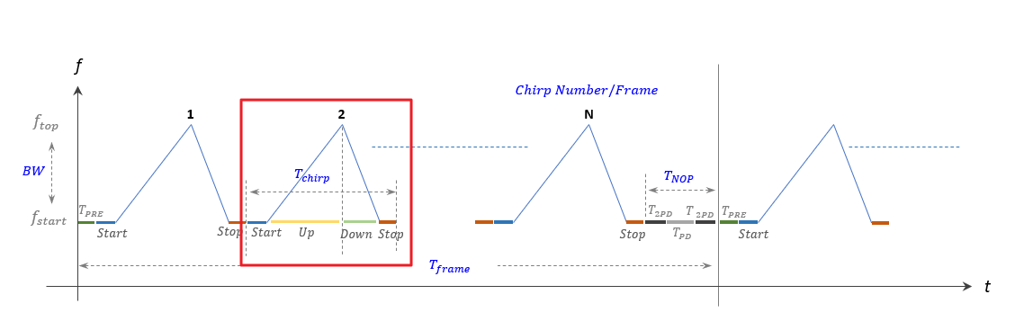
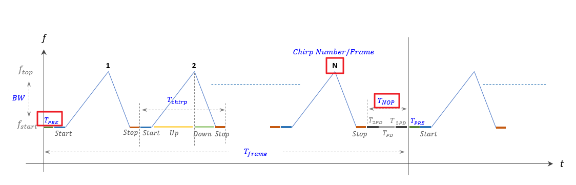
3. Frame Structure
Note. N chirp cycles constitute one frame and to measure speed, data in frame units is required.
| Parameter | Default [us] | Range [us] | Description |
| Chirp No. Per Frame | 32 | >=1 | For setting the chirp number of a single frame. |
| T_PRE Time | 20 | >=1 | For setting head delay of a frame. |
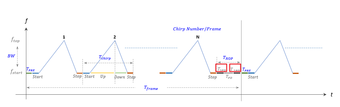
| T_NOP Time | 76 | >=1 |
For setting tail delay of a frame. when in Low Power Mode, must be no less than ( |
4. Low Power Mode
When the box is checked, the chip will enter Low-Power mode during T_NOP.
| Parameter | Default [us] | Range [us] | Description |
| T_2PD Time | 22 |
|
For setting the duration of Low-Power mode. |

WiFi IoT Module
![]()
Bluetooth Module
![]()
5G/LTE/CAT-M1/NB-IoT
![]()